Imagine being able to walk into a building, scan every wall, pipe, and ceiling with a laser, and moments later have a precise, three-dimensional digital replica sitting inside AutoCAD: ready to measure, model, and draw from. That's not a future technology. It's already changing the way surveyors, architects, and engineers work, and it starts with something called a point cloud.
If you've heard the term but aren't quite sure what it means, or you've seen a point cloud in AutoCAD and wondered what to do with it - this guide is for you.
So, What Exactly Is a Point Cloud?
A point cloud is a large collection of data points in three-dimensional space. Each individual point carries X, Y, and Z coordinates, and often additional data such as color (RGB values) or intensity, representing a specific location on the surface of a real-world object or environment.
Think of it like a photograph, but instead of capturing light on a flat plane, you're capturing the physical geometry of the world in three dimensions. Scan a building facade, and you don't get a photo - you get tens of millions of precise coordinate points that, together, form an incredibly detailed 3D representation of that facade's surface.
When rendered in a viewer or inside AutoCAD, these points appear as a dense "cloud" of dots. From a distance, they look almost like a solid object. Up close, you can see the individual points. The density of those points, how many exist per square meter, directly determines the level of detail available for downstream workflows.
How Is a Point Cloud Created?
Point clouds are generated through a process called 3D scanning or laser scanning, and the source technology makes a real difference in the quality and application of the data. The three most common capture methods are:
- Terrestrial LiDAR scanners: high-precision, tripod-mounted devices that emit laser pulses and measure the time it takes for them to return. Used heavily in architecture, engineering, and construction (AEC) projects.
- Drone-mounted LiDAR or photogrammetry: scanners attached to UAVs that capture data from above, ideal for large outdoor areas like topographic surveys, road networks, or open construction sites.
- Mobile mapping systems: scanners mounted on vehicles, used for corridor mapping, road surveys, and utility infrastructure documentation.
Each method produces raw scan data. That raw data then needs to be processed and converted into a usable file format before it can be brought into AutoCAD. The standard workflow involves Autodesk ReCap, which converts raw scan files into .rcs (single scan) or .rcp (project file combining multiple scans) formats, both of which AutoCAD natively supports.
Why Point Clouds Matter: The Scan-to-CAD Revolution
The global LiDAR market was valued at approximately USD 2.89 billion in 2025 and is projected to grow to USD 17.80 billion by 2035, reflecting a compound annual growth rate of nearly 20%. Meanwhile, the global 3D scanning market was valued at USD 5.1 billion in 2024, growing at 11.4% annually through 2034. These aren't abstract numbers, they reflect a fundamental shift happening inside every serious engineering and surveying firm in the world right now.
The reason is simple. Traditional field measurements take time, require multiple site visits, are prone to human error, and often leave gaps in the data. A single laser scan session, by contrast, captures millions of measurements simultaneously, with sub-millimeter accuracy in many cases, and without requiring field teams to revisit the site for clarifications.
For AutoCAD users specifically, this matters enormously. Instead of building geometry from scratch based on manual measurements, you can now work directly from a point cloud that is the reality. Every line you draw, every elevation you extract, every contour you generate is grounded in actual, measured data.
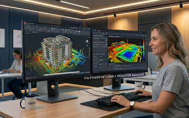
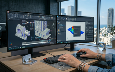
How Point Clouds Work Inside AutoCAD
AutoCAD has supported point cloud attachment natively for several versions. Once you have an .rcs or .rcp file, you can attach it to any drawing via Insert → Point Cloud → Attach, similar to attaching any external reference (xref). The point cloud appears immediately as a 3D reference object inside your drawing environment, sitting precisely where it was scanned in the real world.
From there, AutoCAD's built-in tools give you a solid starting point for working with the data:
- Display control: Adjust point density and point size to balance visual clarity with system performance.
- Color stylization: Apply color mapping by elevation, intensity, RGB scan color, or normal orientation to visually differentiate features within the cloud.
- Clipping and cropping: Isolate specific regions of the cloud to reduce visual noise and focus on the area you're actively working in.
- Segment detection: AutoCAD can identify planar and cylindrical surfaces within the cloud and generate basic 2D geometry from them.
These native capabilities are genuinely useful, but they represent only the beginning of what's possible with point cloud data. In professional workflows, the real work starts after the cloud is attached: extracting accurate geometry, generating terrain models, producing floor plans from dynamic slices, mapping road infrastructure, calculating volumes. That level of work demands more than AutoCAD's native tools were designed to deliver on their own.
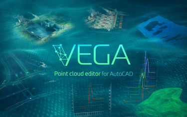
This is where VEGA comes in. VEGA is a point cloud editor built to work directly inside AutoCAD, not as a separate platform you export to, but as a native extension of the AutoCAD environment you already know. It bridges the gap between raw scan data and professional deliverables, giving AutoCAD users a dedicated toolkit for processing point clouds without ever leaving their familiar workspace. If you're serious about scan-to-CAD work, it's worth understanding what that kind of purpose-built environment makes possible, and we'll cover exactly that in the sections ahead.
What Can You Do With a Point Cloud in AutoCAD?
The applications of point cloud data inside AutoCAD are broader than most users initially expect and with a dedicated point cloud editor like VEGA extending AutoCAD's native capabilities, the range of professional workflows becomes even wider. Here are the most common use cases:
Surveying & Topography
- Generate DTM (Digital Terrain Models) and TIN (Triangulated Irregular Networks) directly from ground-level point data.
- Extract contour lines automatically from scanned terrain.
- Calculate cut-and-fill earthwork volumes for site grading and construction planning.
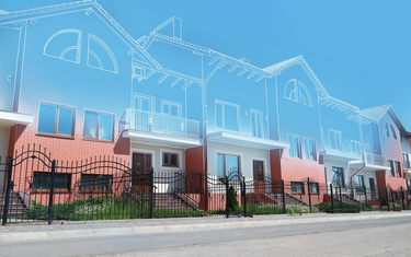
Architecture & Building Documentation
- Draw accurate floor plans by slicing the point cloud at horizontal sections.
- Create extended wall elevations and build facade drawings.
- Document as-built conditions for renovation or BIM delivery.
Infrastructure & Utilities
- Map roads, curbstones, centerlines, and pavement markings from scan data.
- Identify and model cylindrical objects such as pipes, finding center points and diameters with precision.
- Document wired infrastructure: power cables, telephone lines, and drainage networks.
Construction Quality Control
- Check wall flatness and elevator shaft tolerances against design specifications.
- Compare as-built geometry to design models for deviation analysis.
Understanding Point Cloud File Formats
Before you can work with a point cloud in AutoCAD, it helps to understand what types of files you'll encounter:
| Format | Description | AutoCAD Compatible? |
|---|---|---|
| .RCS | Single scan file processed by Autodesk ReCap | Yes |
| .RCP | Project file referencing multiple .RCS scans | Yes |
| .LAS / .LAZ | Standard LiDAR exchange format | Needs conversion |
| .E57 | Universal 3D scanner data format | Needs conversion |
| .XYZ / .PTS | Raw ASCII point data | Needs conversion |
The typical workflow is: scan → import raw data into Autodesk ReCap → convert to .RCS/.RCP → attach to AutoCAD drawing.
Key Terms Every AutoCAD User Should Know
If you're new to point cloud work, you'll encounter a set of terms repeatedly. Here's a quick reference:
- LiDAR - Light Detection and Ranging. The laser-based scanning technology most used to generate point clouds.
- DTM / DEM - Digital Terrain Model / Digital Elevation Model. A 3D surface representing ground topography derived from point cloud data.
- TIN - Triangulated Irregular Network. A mesh surface created by connecting point cloud vertices into triangles, used for terrain modeling and volume calculations.
- Scan-to-CAD - The end-to-end workflow of converting real-world 3D scans into usable CAD geometry.
- Dynamic slice - A horizontal or vertical cutting plane through the point cloud that reveals a 2D cross-section, essential for drawing floor plans or road profiles.
- Point density - The number of points per unit area. Higher density means more detail, but also more processing load.
- ReCap - Autodesk's dedicated software for processing and managing raw scan data before bringing it into AutoCAD.
The Bigger Picture: From Raw Scan Data to Deliverable
Point clouds don't produce final drawings on their own. They are a reference layer: an extremely precise, information-rich one, from which a skilled AutoCAD professional extracts, traces, and constructs the actual deliverable.
This is where the skill gap often shows up. Loading a point cloud into AutoCAD is straightforward. Knowing how to work with it efficiently: how to slice it correctly, how to extract reliable geometry without errors, how to manage the computational load, and how to produce survey-accurate drawings at speed - requires both knowledge and the right tools.
That gap between "I can attach a point cloud" and "I can fully process a point cloud into a professional deliverable" is exactly what modern point cloud processing workflows are designed to close.
Conclusion
Point clouds are fundamentally changing how survey and design professionals interact with the built environment. They replace guesswork with measurement, reduce site visits, eliminate manual re-drawing, and provide a level of spatial accuracy that simply wasn't practical before laser scanning became mainstream. For AutoCAD users, they represent both an opportunity and a skill to develop.
The logical next step: open AutoCAD, attach an .RCP file, and try a dynamic slice - just to see the data in action. Once you do, you'll understand immediately why scan-to-CAD workflows have become the new professional standard.